Lennox Furnace Wiring Diagram 16 G

Wiring Diagram Electrical With Images Electric Furnace

Suzuki Gs400 Wiring Diagram With Electrical Pictures For Gs550

Kinetic Honda Wiring Diagram Chinese Scooters 150cc Diagram

The 16 Best Motorcycle Electrical Wiring Diagram For You With

10 1991 Honda Civic Electrical Wiring Diagram Wiring Diagram In

Unique Circuit Wiring Diagram Wiringdiagram Diagramming

6 flame is sensed gas valve remains open for the heat 2.
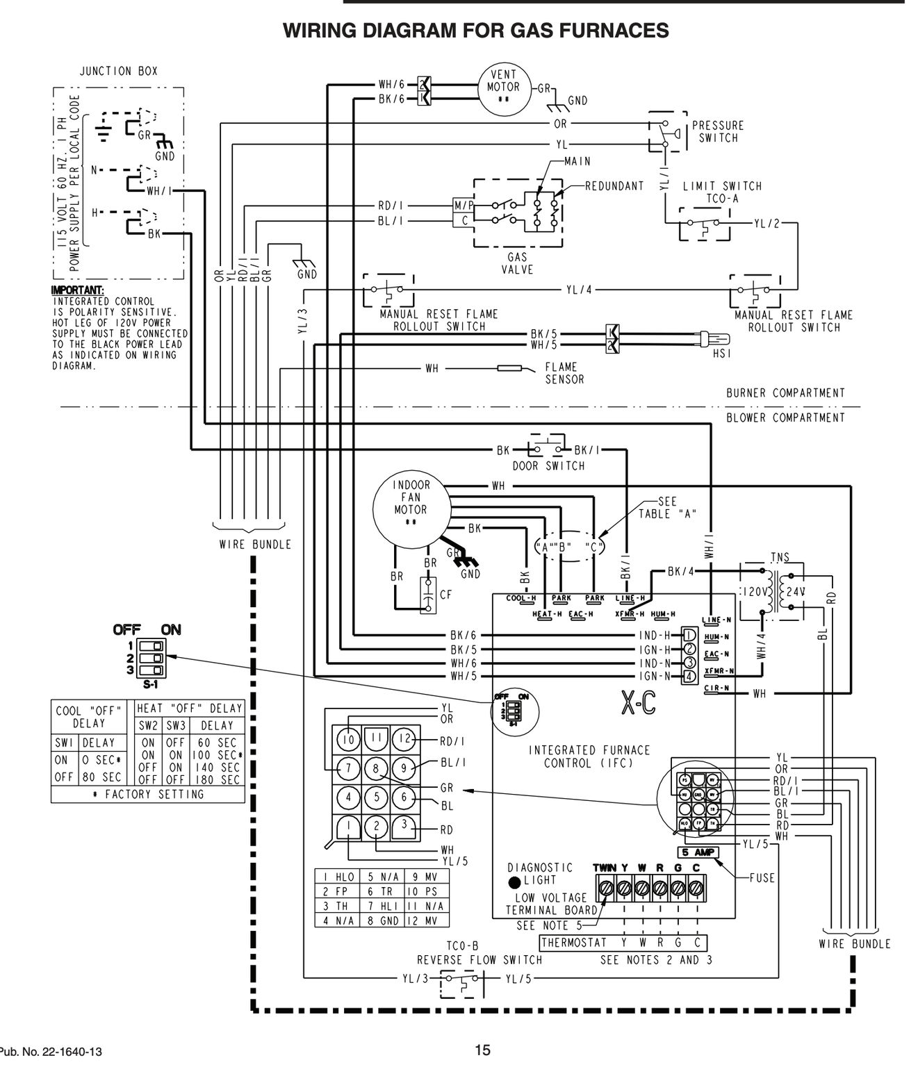
Lennox furnace wiring diagram 16 g. It is a red wire and comes from the transformer usually located in the air handler for split systems but you may find the transformer in the condensing unit. Lennox international inc upflow gas furnace installation instructions g24 200 44 pages furnace lennox g24 200 user s information manual. Color of wire and termination. The sl280uhnv furnace may be installed in alcoves.
Simply narrow your search using the options below. It shows the components of the circuit as simplified forms and also the power and also signal connections in between the devices. Assortment of lennox furnace thermostat wiring diagram. Factory installed internally on left side of furnace.
A wiring diagram is a simplified standard photographic depiction of an electrical circuit. Vii wiring and sequence of operation 1 when there is a call for heat w1 of the thermostat en 5 gas valve opens for a 4 second trial for ignition ergizes w of the furnace control with 24vac. Lennox provides the best in home heating and systems with top of the line hvac systems furnaces air conditioners and many other home heating air products. Note this furnace is designed for a minimum contin uous return air temperature of 60 f 16 c or an inter mittent operation down to 55 f 13 c dry bulb for cases where a night setback thermostat is used.
Lennox ghr32q unit information. Vii wiring diagram and sequence of operation ghr32q 1 unit diagram page 55. R the r terminal is the power. Installation instructions lf24 30 000 to 75 000 btuh series unit heaters 503 526m 10 2006 supersedes 3 01 see unit nameplate for manufacturer and address.
Thermostat wiring and wire color chart thermostat wiring colors code. Collection of lennox wiring diagram. A wiring diagram is a streamlined traditional photographic depiction of an electrical circuit. Field wiring make up box furnished for line voltage wiring.
We ve made it easy for you to find the resources you need including product brochures and owner s manuals. Optional accessories blower relay kit for use with two stage outdoor units allows furnace blower speed changes when matched. Box may be installed internally or externally on either side of furnace.

Cobra Controls Acp 1t 1 Door Computerized Access Control System
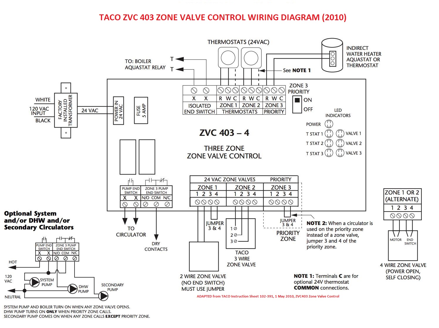
Zone Valve Wiring Manuals Installation Instructions Guide To

17 2002 International 4700 Truck Wiring Diagram Truck Diagram

16 Kia Picanto Electrical Wiring Diagram Wiring Diagram In 2020

12 Giordon Car Alarm Wiring Diagram Car Diagram In 2020 With
Fan Limit Switch Q A 5 Furnace Fan Limit Control Troubleshooting

Gmgm Wiring Harness Diagram 88 98 With Images Electrical

Wiring Diagram Cars Trucks Wiring Diagram Cars Trucks Truck Horn